Tunnel Diode Oscillator - Application of Tunnel Diode
Tunnel Diode Oscillator:
We have already discussed that a tunnel diode is always operated in the negative resistance region. When operated in negative resistance region, the tunnel diode works very well as a oscillator.
In this post let us discuss about one of the major applications of the tunnel diode (ie, tunnel diode based oscillator).
Before proceeding further it is highly recommended to refresh about the Basics, Working Principle and Characteristics of tunnel diode.
Tunnel Diode Oscillator working principle:
Tank Circuit:
The following figure shows a parallel resonant circuit (L-C tank circuit). Remember, the circuit which produces electrical oscillations of any desired frequency is known as a tank circuit or oscillatory circuit. 
The Tank Circuit Working Principle is explained in detail in a separate post. Please Click Here to know about How Tank Circuit Works?
In practical, the inductor will have the parasitic resistance(winding resistance) in it . Including this resistance in the tank circuit, the above circuit will become as follows. 
Here RP is parallel equivalent of the series winding resistance of the coil. When the tank circuit is set into oscillations by applying voltage as shown in below figure, damped oscillations are produced. It is because energy is lost in the resistance RP of the tank circuit.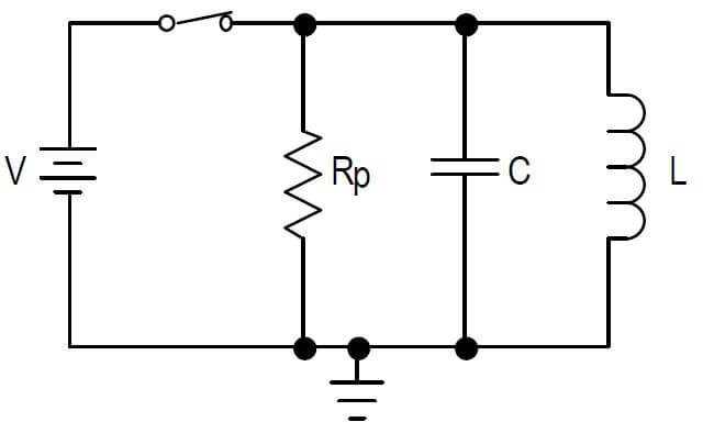 If a tunnel diode is placed in series with the tank circuit and biased at the center of the negative resistance portion of its characteristic as shown in the below figure (marked as a dot), an undamped oscillations are produced at the output.
It is because the negative resistance characteristic of the tunnel diode counteracts the positive resistance characteristic of the tank circuit.
Tunnel Diode Oscillator Operation:
 The above figure shows the tunnel diode oscillator. If the parallel tank circuit (consists of capacitance C, an inductance L and internal resistance RP) connected across the tunnel diode whose negative resistance is –Rn, the net resistance Req represents RP and –Rn in parallel and is given by
If Rp>Rn, then Req is negative and oscillations can build-up.
The oscillation amplitude then grows until it occupies a voltage range greater than the extent of the negative resistance region of the characteristics.
When the operating point enters the region of positive resistance, the amplitude of oscillation is limited.
- To obtain the maximum output, the quiescent point must be accurately located at the center of the negative resistance region. The frequency of oscillation is given by

- A tunnel diode has a characteristic with a negative resistance region between voltage of approximately 0.1 and 0.3V and can be used as an oscillator at frequencies up to 100GHz.
- While the tunnel diode oscillator works very well at very high frequencies (in mega hertz range), it cannot be used efficiently at low frequencies.
- This is the major drawback for the tunnel diode oscillator which is also known as negative resistance oscillator.
Thanks for reading about Tunnel Diode Oscillator... Please subscribe to get new posts to your mail id.....
Read More:
Crystal oscillator - Basics, Working, Frequency Response
How Tuned collector oscillator works? - Circuit Operation, Working Principle
Colpitt's Oscillator Working Principle
Induction Motor Speed Control Methods
