Electronics Mini Project for Diploma Students
Electronics Mini Project for Diploma Students - 1
Light Based Alarm Circuit Using Opamp
In this post we are going to do a simple projects with the help of few components along with Opamp-Comparator IC.
Required Components to execute the Project:
- Regulated Power Supply (28VDC)
- Voltage Regulator IC - 7815, 7915
- Comparator IC - LM2903
- Light Depended Resistor (LDR)
- LED or LCD Display or Relay
- Resistors
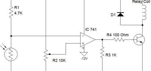
 As shown in the figure, the Comparator IC compares the voltage V1 with the reference voltage (V2).
 - In this circuit the value of V2 is zero (V2 = 0).
- The LDR (Light Dependent Resistor) and the Resistor (R) form a voltage divider circuit.
- The voltage at this voltage divider junction is nothing but V1 . It is fed to the inverting terminal (pin-2) of the comparator IC. This voltage is compared with the non-inverting terminal input voltage (V2).
- During normal room condition (bright light condition) the resistance of the Light Dependent Resistor(LDR) will be very less (in the range of milli ohms).
ie, resistance of LDR is less than resistance of R.
ie, voltage across R is more than that of voltage across the LDR.
ie, V1 is more than V2(oV).
ie, inverting input is more than non-inverting input. - So the output voltage will be -15V which will not turn on the LED.
- In conclusion, the LED will not ON during normal room condition (bright light condition).
- During dark condition, the resistance of the Light Dependent Resistor(LDR) will be very high ( in the range of mega ohms). ie Resistance of LDR is much higher than that of resistance of R.
- So more than 30V will be dropped across the LED in the voltage divider.
- It means voltage V1 will fall below 0V.
- In simple, during dark condition the voltage V2 > V1.
- So the output voltage V0 will switch from -15V to +15V. Thus the LED will glows.
- If the place where the LDR kept becomes dark, we will come to know by observing the LED turn on/off status.
Now the big and very important question is How to use this concept?
Please refer similar kind of project done using 555 timer IC in our previous post. Click here to know about the 555 timer based warning light Mini Project.
This project will replace the 555 timer warning light circuit. For reference, the same block diagram is given below:

Electronic_detector_Alarm_Block_Diagram
This circuit can be used to detect if any person enters across the light beam(comes from light source to LDR). So if this light beam is kept at the door entrance, whenever a visitor comes inside the premises, the receptionist gets a notification in her place.
Welcome Board Display Mini Project:
- You can modify the above circuit by replacing single LED into a LCD display in the opamp output stage (Change the value of output resistor accordingly).
- Then we can use this project to greet the visitor.
- Whenever a visitor enters into the premises the light beam will be interrupted. ie LDR changes from normal room light condition into dark condition for a moment.
- During that time, the Liquid Crystal Display Welcome board will glow.
The modified circuit is shown below:
 Based on our creative knowledge to place the LDR and light source, we can implement this circuit in numerous real life locations.
Vehicle Detector and Gate Open Project:
- For example, in-car parking entrance we can implement this circuit.
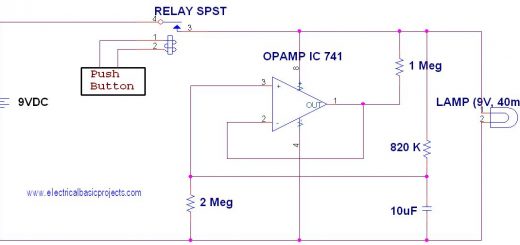
- To do that you have to modify the above circuit by replacing output LED into relay (Change the value of output resistor accordingly).
- The output of the comparator IC is given to the relay coils.
- The relay will be Normally Open type. ie if the coils are not energized, the contacts will be in open position.
Operation:
- Whenever the car comes and waits in the entrance of the car parking station, the light beam is blocked.
- Eventually, the LDR is in dark condition and the output of the comparator is high (+15V).
- It will energizes the relay coil.
- So the NO contacts moved to NC condition and which lifts the barrier.
- It allows the car to enter inside the parking station.
You may also like to try:
Electronics Mini Projects using OPAMP
Simple LED Flasher Circuit
Frequency to voltage converter Concept Based DIY Project
Thanks for reading... Please try this project... if you face any difficulties please share with us...

i will try led glow as "welcome to our college"
how its work pls explain its application in routing life
what value can we take for resistor(R) in Light Based Alarm Circuit Using Opamp